Selecting the right TIM (Thermal Interface Material) for your project.
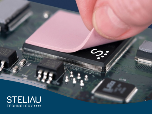
Choosing the right TIM for your design can be just as critical as choosing the component it will act on and the radiator it will dissipate heat to.
Any engineer who has tackled the calculations for a design with a critical thermal component for the first time, whether due to the application, the component's location, or its high power consumption, is faced with a wide range of materials, radiator shapes, and fan options that can be overwhelming.
In this situation, or when we encounter problems in solving the stress and aging that can occur on a component or board if they are subjected to high temperatures, expert advice can offer appropriate solutions for each case. The team of engineers at Steliau Technology's Thermal & Adhesives division has been contributing its experience since 1992, using the latest technology to verify the suitability of solutions, as well as equipment to design and manufacture these solutions in forms that are fully customized for the application.
Why use a TIM?
Materials are not completely smooth when we look at the junction between the component and the radiator at a microscopic level, and even if we press one material against the other, we can see that the irregularities form small air bubbles between the two surfaces and the contact is not as direct as it appears to the human eye.
As the thermal transmission index of air is very low compared to other materials, it is necessary to eliminate it and homogenize the surface so that there are no contact points but rather a contact surface. We achieve these effects by using a TIM (Thermal Interface Material), which is basically a thermal material that, due to its physical characteristics, molds itself to the nanometric irregularities of the surfaces.

What information is needed to choose a TIM?
At this point, we face the dilemma of what type of material to use. The answer is not easy. If we look at the Steliu Technology catalog, it has 2,000 references in stock, and the selection depends not only on the thermal conductivity of the material when we want to dissipate heat or the thermal resistance when we want to insulate (Figure 2), but we must also take into account data such as:
- Contact pressure.
- Surface roughness.
- Whether the surface is completely flat. (Difference in height between components on the PCB)
- Time.
- Temperature.
- Material thickness.
-
Filling attributes.
Therefore, before deciding which material to use, we must answer certain questions:
- - What are the components between which the TIM is located? “Component to be cooled and heat sink that has been decided to be placed.”
- - Are the components in contact or is there a gap to fill?
- - How thick is the gap between the component and the heat sink? Nominal + min. and max. tolerance.
- - How is the component mounted on the heat sink? Screws, clips, etc.
- - Is there an impression and/or dimensions of the TIM available? Depending on the materials, this will allow us to make a component-specific element, saving material and cost, as well as guaranteeing the quality of the final product.
- - What is the total heat/power (in W) generated by the component to be dissipated?
- - Is a thermal resistance (Rth) or thermal conductivity value expected from the TIM?
- - Is electrical insulation required?
- - EAU/SOP project data, sample/prototype, and L/T
With this information, we can now look at the range of TIMs to use:
Thin interface pads are a standard product with high thermal conductivity, performance levels of 0.8-3.0 W/m-K, film and fiberglass reinforcement that may or may not contain silicone, and conductive or electrically insulating versions. It is often used in applications that require high dielectric strength, but it should be noted that it requires firm pressure to maintain its effectiveness.
A key advantage is that the pads can be designed to the shape or size required by the application; Steliau Technology has a design team and machinery to meet the needs of the equipment or system.
Phase change pad where the viscosity of the material changes depending on the temperature (around 50-60ºC). Depending on the product range, it can be found in traditional pad format or as so-called high-performance greases. This variety allows us a performance range between 1.0 - 4.0 W/m-K, which is why it is often used in high-computing applications. To use these pads, the assembly process must be clear, as the placement of screens, templates, and pads must be planned, as well as the electrical insulation requirements.
Thermally conductive putty is also a standard product with performance levels between 1.0 and 8.0 W/m-K, which can be found as curable materials (using two components) or pre-cured materials (a single material). Both formats offer solutions with and without silicone.
Its use is recommended for large production volumes, and a material dispenser is required for optimal use.
The use of this solution has the fundamental advantage that the pressure exerted on the TIM has virtually no effect on its deflection compared to conventional pads.
These compounds are evolving thanks to research into new materials to provide higher thermal performance and greater softness, or what this characteristic implies, greater reworkability.
Gap Pads are pads that not only allow heat dissipation, but also level areas in mixed component layouts on a PCB. Standard materials with thermal conductivities between 0.8 and 20.0 W/m-K and thicknesses of up to 6.5 mm are available, with or without a silicone base.
Their design is tailored to the application in terms of both shape and thermal conductivity. One of the advances being promoted in the materials industry is the combination of thermal performance with EMI absorption, making this type of solution very attractive for all kinds of applications.
Applications and Support
With this variety of thermal performance and material solutions, the applications for these components range from the power segment with power supplies, DC/DC converters, battery chargers, UPSs, induction elements, pumps, EV equipment, dissipation for power LEDs, induction elements, household appliances, and much more. Covering vertical markets such as industry, medical, Hi-Rel, telecommunications, lighting, and transportation.
Each market and each application has its own unique and special characteristics. With 20 years of work, the Steliau Technology team has gained experience and know-how that allows it to reduce product development costs, offer CFD analysis, as well as consulting for the best recommendations in thermal solutions and support for new products that need a thermal solution or to solve problems in existing products.
Our advanced simulation software allows us to perform thermal modeling and use advanced computational fluid dynamics (CFD), creating accurate models of electronic equipment that enable specific designs for the electronics industry. This software is adapted to overcome thermal design challenges, helping the team led by three specialized engineers from Steliau Technology's Thermal & Adhesives division to provide unbeatable solutions.